Can-Am ATV & UTV Forums banner

04' Traxxter (John Deere Buck) Multiple Issues

8.1K views 25 replies 4 participants last post by  markfothebeast01  
#1 ·
I can't recall if this is a 400cc or a 500cc Rotax model but it is liquid/fan cooled. Short story; neighbors left it out in the woods/farm unused for x amount of years. They kindly let me keep it over at my house to use it but it suffers from electrical issues and a failed gauge cluster circuit board.

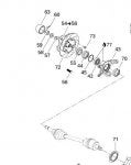
Drove it a few times to pull stuff. I heard a front CV axle clicking. Neighbor kids wanted to use their ATV so I let them take it. They beat it until the CV finally let go. I went back over there and brought it back home. You can imagine what the neighbors barn looks like...A graveyard of abused machines. So now I have 2 major issues. I need to fix the gauge cluster circuit board and (2) repair the CV axle.

I'm not putting any money in this machine. The gauge cluster is $320... Not sure what a front right CV axle cost but I'm not investing anything other than fluids and labor.

I'm not all that familiar with ATVs but I am experienced in automotive and electronics repair. I fixed multiple wiring issues in this Traxxter already. It's actually a John Deere Buck but it is the same machine. Are the CV axles repairable? I have a press but have never pulled one of these apart... It is completely disconnected and flopping around.

As for the gauge cluster, it was ruined by the elements. A SMD capacitor fell right off when I pulled the PCB out. I'm going to try to reflow the circuit board and re-attach the capacitor with a SMD soldering station. Hoping this works because there are some functionality problems without the cluster. It does drive and shift without it, although. But first I need to devise a plan to repair the CV axle.

Sent from my SM-G920V using Tapatalk
 
#6 ·
As a temporary fix, you can remove the inner boot clips and boot. Remove the inner race of the joint and remove the axle.

The inner joint in the diff is held in by a small clip. You'll need to leave the outer joint in place if you're going to ride it, as it holds the wheel bearing together.

If the spline on the shaft is still ok, you can simply buy a new/2nd hand outer joint and repack the inner.
 
#12 ·
This may help explain how it's all held together.

attachicon.gif
Capture.JPG

#59 is the axle nut. It threads onto the end of the outer cv joint and holds all the wheel bearing and brake disc together.
The cv shaft isn't pressed into the hub, it just slides through the bearing etc and the nut gets done up.
Thanks. I forgot I had the service manual. Once I get the time to to take it all apart I'll have to see what's missing or failed in the joint. If the hub is still sealed and the joint just pulled apart I'll fabricate something up. I'll update with more pictures when it's apart.

Sent from my SM-G920V using Tapatalk
 
#13 · (Edited by Moderator)
I lifted the front end tonight and holy balls, this thing is in rough shape. Of course, it is/was a farm vehicle and they are recyclable to farmers that have no time to repair small farm equipment. It has the John Deere name... If it were an Arctic Cat it'd be done for. The abuse this thing has taken surprises the hell out of me that it is STILL running! This Rotax engine makes me want to buy a Can Am if I pursue an ATV in the future.

Anyhow, on this model the CV axle does not appear to support the wheel hub assembly. That would be a lot of stress on the CV joint. The hub appears to be pressed in. The axle nut (just like a FWD car) keeps the CV tight in the hub. The control arms as well as the ball joints support the hub and wheel. I had no choice but to chop the CV axle rod off to make it drive-able. The CV ball bearings are gone...out in a corn field somewhere.

If it were mine I'd be fabbing some tougher suspension up. I had to tighten a lot of nuts and bolts. The next step is to manually wire up the winch. I believe they are a 6 pole switch. I'll have to look into that one again...

Sent from my SM-G920V using Tapatalk
 
#21 ·
I do have a question about the diagnostics connector that the service manual doesn't clarify very well.

There's a diagnostics connector on the rear of the frame on the left side (looking at the rear). Does this need to be plugged in or unplugged for diagnostic mode? It was plugged in already.

Question 2: I want to replace the headlamps bulbs and use some left over halogens from a car which are 45w low/65w high. The OEM bulbs are 30w halogens. The service manual mentions that the MPEM controls the bulb intensity. Is this going to be an issue with that? The bulbs may be too hot for the housing as well.

The next project is to replace the old ATV battery that's causing issues with the MPEM (low voltage). I plan to run 2 gauge wiring to the front storage compartment and use a sealed automotive battery since I have so many extra batteries. This should help considerably with the power draw from the winch.

Sent from my SM-G920V using Tapatalk
 
#22 ·
The diagnostic jumper they sell jumps the terminals in that connector and completes a circuit. I made one. Took 5 minutes.
Yours probably just has a plug to preserve the connection from the weather.

I might work with the headlights. I don't think so.
The bulbs in there only have one filament. It doesn't change filaments to change beams. It adjusts the power to give you hi and low.
It may not be able to control both filaments of a typical halogen.
Try it.
I'd just add a small led bar to be honest. Traxter headlights are decent, better than outlander by a good bit. Leds, even cheap China leds are so much better though, for not much money.

Sent from my iPhone using FBI server.
 
#23 ·
The bulbs look like they have 2 filaments and 3 terminals just like a car halogen. But I'm not going to mess with it.

The jumper is there. It is hardwired in as the service manual mentions. I found that someone thought it was supposed to be connected.

It's a fairly simple machine to work on. I just wish the cluster worked so I could understand what it's trying to tell me. I have no flashing gear lights anymore near the shifter. It shifts smoother as well. I have the schematics to jump an LED between the "Check Engine" LED terminals but haven't done it yet.

I spent the entire day cleaning the ground/positive connections and installing 2g wiring to an automotive battery in the front compartment. That pretty much did the trick for the electronics. The computer is very sensitive to low voltage. So now the winch has the extra amps it needs too.

Sent from my SM-G920V using Tapatalk
 
#24 ·
The computer is also very sensitive to too much power.
Don't ever hook that machine to something to jump it.
You'll fry your mpem, then you are done. Lots of money for a new one.
When I get my traxter back out here soon I'll look at the bulbs.

Overall it's a good machine, and pretty hard to kill.
Weird about your diagnostic port.
I have two traxters, they just have a plug. On the left back there.

Watch eBay, they get sorted out occasionally. I've seen every part show up over the years, even clusters.

Sent from my iPhone using FBI server.
 
#25 ·
I haven't "jumped" the machine per say by pumping amperage through it but rather connect a battery to the existing battery. This allows the system to draw the amperage it needs. I always give it a bit of time to allow forward voltage to enter the battery. The service manual is very clear as well about not jump starting the machine.

Sent from my SM-G920V using Tapatalk